Programed Repairs Engine 103 Combustion KE Injection
WIS Prog_Repairs-comb4
14 Emissions control system, intake manifold, exhaust manifold
Complaint:
Leak in intake manifold gasket
When installing, the metal side must face toward the exhaust manifold. Cause Prior to September 1985 the M8 x 40 securing bolts installed may be too short. Remedy Install M8 x 45 securing bolts, part no. 000933 008119 with spring washer, part no. 000137 008204.
Compiaint:
Front passenger footwell heats up considerably because of catalytic converter
Cause/Remedy
1 Check clearance of heat shield (above catalytic converter) to floor of car. Specification: 8 – 9 mm; adjust to correct clearance, if necessary.
2 Place glass fiber mat, part no. 000 989 18 10 (available only in square meter sections), below footmat.
Note Model 124 RUF/KAT: glass fiber mat standard in front passenger footwell since 07/88. Production breakpoint as of vehicle ident end no. A 798379 and B 0822339, respectively
Complaint:
Leak at ball flange of exhaust manifold
Cause Exhaust manifold twisted. Remedy Install exhaust manifold part no. 103 140 08 14 and 103 140 10 14 with new collar nuts. Check front exhaust system for signs of twisting, replace if necessary. If front exhaust system on the models 126.020/024/025 is twisted, install new exhaust system part no. 126 490 07 20 and bolts 129 990 03 10.
wie = RA 07.3.1142/1 PR
Complaint:
Exhaust system (KAT) making contact with yoke of front axle
Model 126
Cause Bell of front exhaust system widened or twisted (oval-shaped bell). Remedy Replace front exhaust system and check exhaust manifold for twisting. (Installl new collar nuts at exhaust manifold.)
15 Electrical system engine (ignition system)
Complaint:
Engine cuts out when accelerating, has poor throttle response, occasionally stops
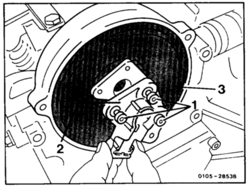
Cause 1. Ignition spark occasionally jumps to ground within distributor rotor arm. 2. No carbon in distributor cap or distributor cap scorched at carbon mount.
1 Securing screw 2 Distributor rotor arm 3 Sealing plate
Remedy 1. Remove distributor rotor arm. If signs of scorching are visible on the flange on the rear, replace. In order as of 03/86. 2. Replace distributor cap. Production tolerances modified as of 01/86.
A When removing and installing the distributor cap, it is important to ensure that the carbon does not strike the dome of the rotor arm and is damaged.
time §=RA 07.3.1142/2
PR
Complaint:
Engine occasionally does not start, or cuts out
Cause Crankshaft position sensor (L5) has occasional open circuit or short to ground.
Remedy Check crankshaft position sensor (L5) (15-1250).
Complaint:
Engine cuts out when accelerating, occasionally stops
Model 126
Cause Corrosion at connector of supply for EZL ignition control unit. Remedy Clean the terminals of the EZL ignition control unit with contact cleaner and cotton tabs. Replace the wiring harness part no. 126 540 72 34.
A When routing the wiring harness, ensure that the lacing of the cable for terminal TD is laid not up, but down to ensure that no water can flow into the wiring harness and to the connector.
| Complaint: Poor cold starting characteristics Engine 103 except 103.980 | |||
| Remedy Install spark plugs with low thermal value (standard from about 02/87), see 15-1031. Spark plugs | |||
| Engine | Beru | Bosch | Champion |
| 103 RUF/KAT | 14 K-8 DU/DUO | H 8 DC/DCO | S 10 YCC |
wii =RA 07.3.1142/3 PR
Complaint:
Loud knocking noises from engine compartment in the area of the ignition coil
Cause Iron cores of the Bosch ignition coils poorly bonded. This results in knocking noises at the ignition coil when the engine is running. This complaint relates to ignition coils with production date FD 845 – 847.
Remedy Install ignition coils prior to production date FD 845 or after FD 847.
Complaint:
Engine cuts out when accelerating, ignition timing varies greatly (jumps)
Cause Irregularities in the voltage curve of the position sensor occur as a result of an excessively rough surface of the segments at the flywheel. In the case of Bosch EZL ignition control units, this can result in undefined ignition timing levels.
Remedy Install corresponding Siemens EZL ignition control unit.
whine §=RA 07.3.1142/4 PR
Complaint:
ASR indicator light comes on when driving and electronic accelerator pedal moves into
emergency running mode (cannot easily be depressed after short idle travel)
Engine 103 with ASR
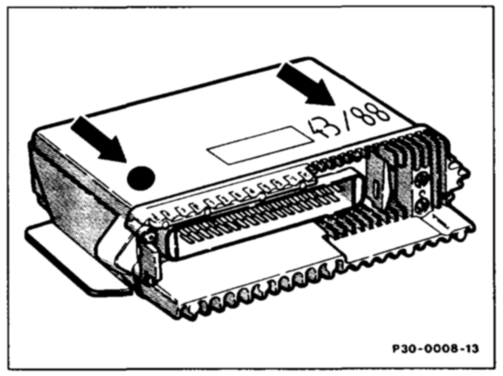
Cause/Remedy 1. Control unit of electronic accelerator pedal.
Check production date of control unit part no. 126 545 07 32 (see ill.). Control units with production dates from 16/88 up to 43/88 must be replaced with a contro! unit as of production date 44/88 (identification: yellow dot) or by the control unit part no. 126 545 08 32 (as of August 19839) if this fault occurs.
2. Check accelerator control, adjust (30-1010).
3. Replace position sensor (R25).
Complaint:
Jerking during load changes
Models 124 and 201
This complaint relates to the engines in the models 124, 201 with manual transmission and LHD version.
Remedy Part no. Install modified accelerator pedal lever. Model 124 201
Adjust accelerator control (30-1010). Accelerator 124 300 04 25 201 300 09 25 pedal lever Bush 124 301 0418 201 301 03 18
Stop 124 300 01 41 124 300 01 41
wie RA 07.3.1142/5 PR
Production breakpoint: 11/88 Model Vehicle ident end no.
124 A 907 056 F 096 908
201 A 473 115 F 576 183
Complaint:
Cruise control does not operate. During adapter test, LED for speedometer shows steady light, in contrast to the information on the test card (only with speed-responsive volume
control for Becker Elektronik radio)
Model 126.
Cause . 1. Blue control cable from cruise contro! connection and speedometer to volume contro! of radio has short to ground. 2. Volume contro! faulty.
Remedy 1. Test blue control cable for volume control for short to ground; repair if necessary. 2. Replace volume control of radio.
Complaint:
Electric cruise control: changes in speed (Surging) of about 2 – 3 km/h at intervals of 3–4 s.
This relates to the 50 – 80 km/h speed range
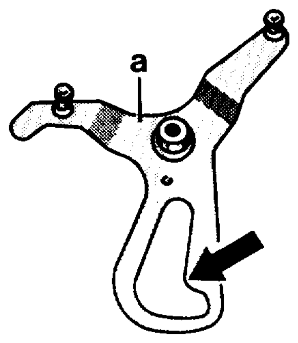
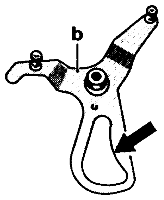
Cause Shape of the fulcrum lever. Remedy Install new fulcrum fever, part no. 103 070 28 21.
Production breakpoint: phased in from 11/85
a 1st version b 2nd version :
wie = RA 07.3.1142/6 PR
Complaint:
Vehicle jerks when cruise control switch is held in „Decelerate” position
Engine 103 without ASR
Remedy Set connecting rod of accelerator control actuator about 2 – 3 mm or 2 – 3 turns shorter.
Complaint:
Car runs about 10 km/h beyond the set speed; in addition, jerking may occur at higher speeds Vehicles (without ASR) with cruise control from about 01/89
This complaint relates to vehicles with reference connector the Tempomat cruise control unit.
Cause Contact resistance at the connector pins for the reference connector.
Remedy Remove black rubber seal between control unit and reference connector and install in its place a new grey rubber seal. Request parts from VP/SPB.
Production breakpoint Control unit with modified rubber seal (grey): 12/89.
wie RA 07.3.1142/7 PR
Complaint:
Cruise control surges by 5 to 7 km/h over entire speed range
Note The fault can be clearly felt when the speed is increased with the cruise control switch. The vehicle accelerates further by about 5 to 7 km/h after the switch is released, speed drops off again and the speed change then occurs constantly.
Cause Cruise control unit faulty.
Remedy Test cable harness for short circuit. If cables are o.k., replace actuator and then cruise control unit.
Complaint:
Cruise control sometimes does not operate
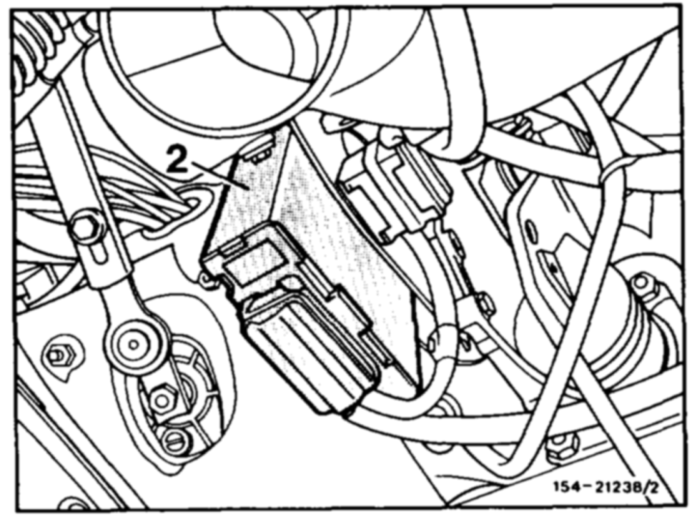
Cause Poor contacts at the control unit (2) as a result of the sockets widening.
Remedy Bend in sockets; ensure that the connector is correctly assigned.
Location on model 107
wi RA 07.3.1142/8 PR
Complaint:
Electric cruise control cannot be set, switches off when driving or vehicle jerks Model 124
Cause Road speed signal from Hall sensor at instrument cluster has occasional open circuit.
Remedy Install improved Hall sensor, part no. 007 542 29 17, as of production 06/88.
Complaint:
Electric cruise control: vehicle on flat road up to 65 km/h and when climbing hills Models 107, 124, 126 up to about 09/87
Cause Decel fuel cutoff is not deactivated when cruise control operated. Can be checked by disconnecting the coupling of the decel fuel cutoff microswitch (S27/2) at the fulcrum lever. The jerking then no longer occurs.
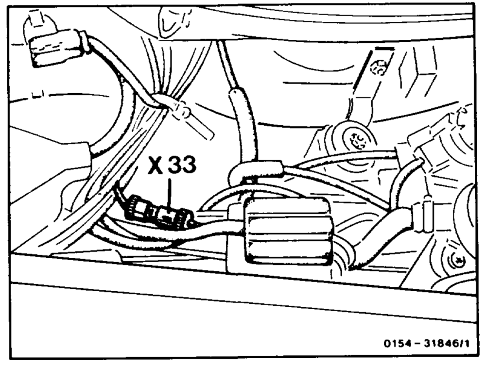
Remedy 1. Test the plug connection of the white wiring X26 (contact 11) or X33. If the plug connection X26 (contact 11) or X33 is not plugged together, the ends of the cables are at the following points:
| Model | End of cable of engine harness | End of cable of cruise control harness |
| 107 | Tied back in engine compartment in area of plug connection of cruise control actuator at wiring harness | Loose in area of diagnostic socket |
| 124 up to about 08/85 | Tied back in fuse/relay box about 150 mm __ Loose in fuse/relay box form plug connection X26 at wiring harness | Loose in fuse/relay box |
| 124 as of about 09/85 | In fuse/relay box in plug connection X26 contact 11 | Loose in fuse/relay box |
| 126 | Tied back in fuse/relay box at wiring harness | Loose in fuse/relay box |
iim =RA 07.3.1142/9 PR
2. If point 1 is in order, test white cable on model 107 between plug connection of actuator (contact 7) and coupling of KE control unit (contact 6) or models 124, 126 and 201 between coupling of cruise control unit (contact 5) and coupling of KE control unit (contact 6) for open circuit. 3. If items 1 and 2 are in order, replace KE control unit.
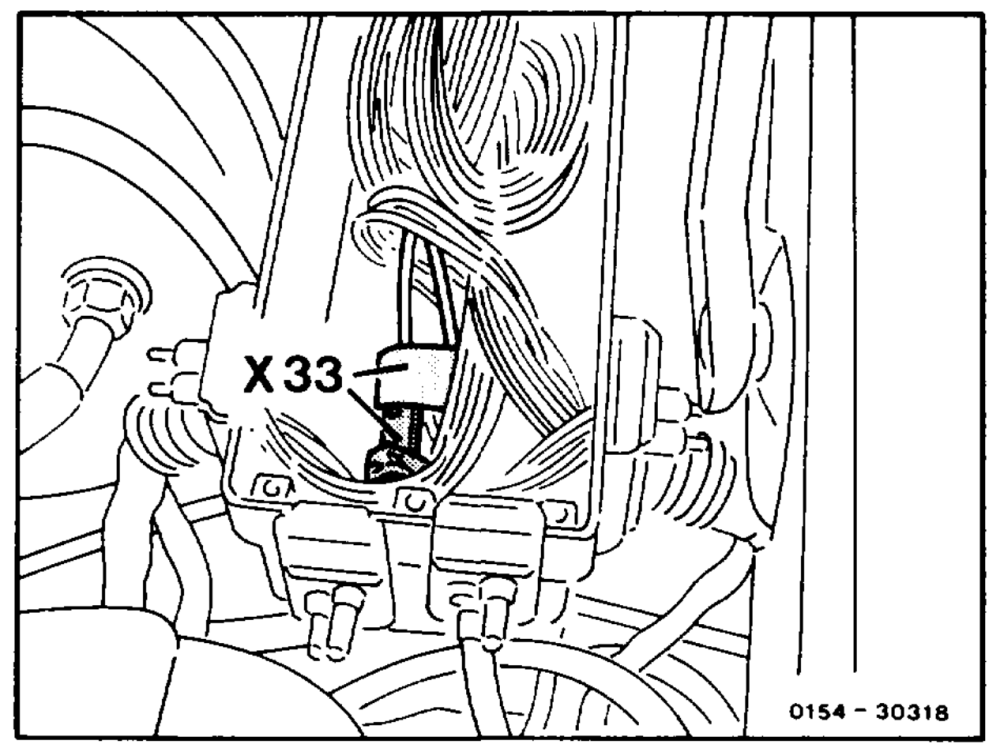
Location X33 on model 107 in area of plug connection of cruise control actuator
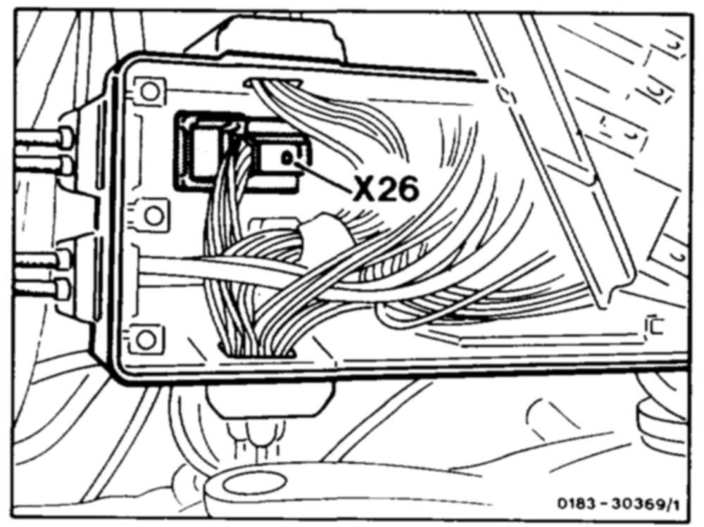
Location of X33 on model 124 up to about 08/85 in fuse/relay box
Location of X26 on model 124 as of about 09/85 in fuse/relay box
wim §=RA 07.3.1142/10 PR
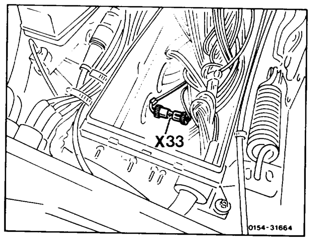
Location of X33 on model 126 in fuse/relay box
Complaint:
Cruise control does not operate after replacing or installing a control unit,
part no. 005 545 05 32, up to production date 08/88.
Cause Bridge in control unit from contact assignment 13 to 14.
Remedy Remove ground bridge in the 14-pin connector for control unit from contact 12 to contact 14. Connect ground cable or cables to contact 12. Contact 14 is no longer assigned.
wie RA 07.3.1142/11
PR
Complaint:
Fuel hose between fue! pump and fuel tank has chafing points
Model 201.029,
Cause Minimum clearance of 20 mm between fuel hose (intake hose) and the inner ring mass of the left input shaft not maintained. The vehicle must be standing on its wheels ready for the road in order to check the clearance.
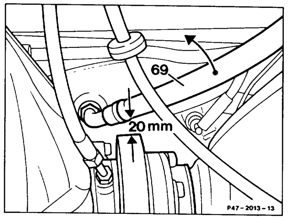
Remedy Correct the routing of fuel hose. 1. Disconnect ground cable of the battery. 2. carefully drain fuel tank (Atlas Copco delivery pump). 3. Detach fuel hose (69) at the fuel strainer, collect the remaining fuel. 4. Swivel fuel hose (69) in direction indicated by arrow until clearance of 20 mm is achieved. Tighten bolt connection (28 Nm). 5. Fill fuel tank as specified (see above for pump). 6. Connect ground cable of battery. 7. Run engine for a short time. 8. Check fuel hose connections for leaks.
The fuel hose must be replaced if it has visible signs of chafing.
wae =RA 07.3.1142/12 PR
Complaint:
Smell of fuel in trunk
Model 124 Sedan/Coupé
Remedy Install fuel hoses in improved quality and sheet steel expansion tank, part no. 107 470 07 89. When replacing parts, only the fuel hose approved for model 107, part no. 107 476 37 26, may be installed between fuel tank and fuel expansion tank.
Production breakpoint: Expansion tank 01/85 as of vehicle ident end no. A 024 253. Fuel hoses 06/85 as of vehicle ident end no. A 032 140.
Complaint:
Engine misfiring when reserve quantity in fuel tank and when cornering
Mode! 124 Sedan/Coupé
Remedy Install new fuel tank with production date as of 01/88.
Production breakpoint: 01/88; vehicle ident end no. A 667677
Complaint:
Slopping noises
Models 107, 124 Station Wagon
Remedy
Fuel tank
install fuel tank with sound-deadening shell. Model! Part no.
107 470 42 01 107 Identification feature (model 124 Station Waqon) @ 4mm hole in left, rear edge 124 Station Wagon 124 470 53 01 Production breakpoint as of vehicle ident end Engine with gasoline injection no.: Model 107 A 069 655 (May 1987) Model 124 Station Wagon F 022 693 (October 1986).
PR
wile §=RA 07.3.1142/13
Complaint:
Splashing noises
Cause Splashing noises are produced in the fuel tank because of the formation of vapor bubbles in the feed pipe. Remedy Install fuel tank with vapor bubble separator. Models 124, 201, no remedy planned.
Production breakpoint:
Fuel tank
Model 107 = 05/87, as of vehicle ident end no. Model Part no. A 069 655 107 107 470 42 01 Model 126 = 03/87, as of vehicle ident end no. 126 126 470 40 01 A 327 880 (only vehicles with V8 engines)
PR
wii =RA 07.3.1142/14
Complaint:
Crackling noises, fuel tank compressed or leaking (smell of fuel)
Models 124, 201 with fuel evaporation control system
Cause/Remedy Insufficient ventilation of fuel tank through fuel evaporation contro! system.
1st cause Poor routing of hoses (kinked, crimped) in left, front wheel arch. Remedy Remove bulkhead of left, front wheel arch. Perform visual check, ensure hoses are not blocked (do not use compressed air). Rectify any fault.
2nd cause Activated charcoal filter is blocked or has only insufficient clear passage. Remedy Blow through @ 10 mm connection to @ 8 mm at activated charcoal filter (not with compressed air). At the same time hold @ 6 mm connection closed. Compare with new activated charcoal filter if necessary. If clear passage is not sufficient, replace activated charcoal filter.
Check fuel evaporation control system, 47-8201.
Additional check when enaine at operating temperature: Detach vent valve at fuel tank. Connect tester (vacuum/overpressure) 201 589 13 21 00 to the vent valve. Start engine and slowly increase engine speed to about 3000 rpm. When this is done, no vacuum must be indicated.
Complaint:
1. Smell of fuel in trunk
2. Loud slopping noises in fuel tank
Mode! 201 with plastic fuel tank
Remedy Install sheet steel fuel tank.
wim §=RA 07.3.1142/15 PR
Complaint:
Smell of fuel in garage or at tail of vehicle
Model 201
Remedy Check fuel hose between fuel tank and pump set (suction hose) for signs of leaks; replace if necessary.
Complaint:
Slopping/Splashing noises when fuel tank full or 3/4 full
Model 124 with 90-liter tank
Cause Noises of this nature may occur as a result of the larger fuel tank. Remedy None
49 Exhaust system
Complaint:
Irregular, loud crackling or rustling when the engine is switched off after driving fast
Cause The two-shell design of the front muffler and the high temperatures at which it operates, result in stresses when it cools down, which in turn cause this noise. A further cause is the high level of heat radiated by the front muffler to the heat shield.
Remedy No remedy is possible on the basis of the present state of the art. The problem does not affect the life of the exhaust system.
wilme =RA 07.3.1142/16 PR
Complaint:
Trunk floor heating up in the area of the left wheel well
Model 129
Remedy @ Check clearance from the tail muffler to the heat shield (specification about 25 mm) and from the heat shield to the floor of the car (specification about 10 mm); correct if necessary. ®@ Modified sound proving mat in left of trunk (part no. 129 680 09 25). Production breakpoint: 02.03.90. @ Trunk floor covering (part no. as before) with sound proving lining on the underside. Production breakpoint: 01.02.90.
Complaint:
Steering wheel vibration
Model 129
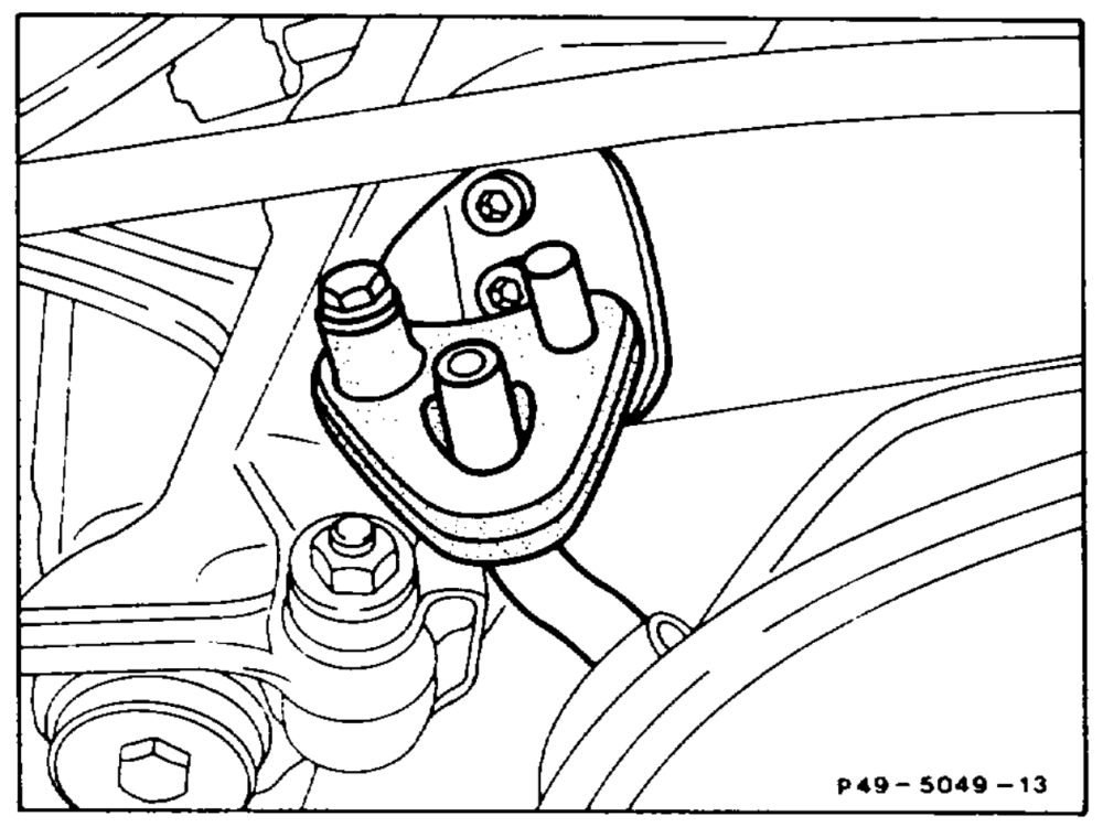
Remedy Install modified rubber ring at center muffler on left (Fig. 1). On vehicles without KAT, install additional fixture with rubber ring to the left front muffler (Fig. 2). Attach the top bracket with the front, left bolt of the tunnel closing plate. Weld the bottom bracket to the left exhaust pipe.
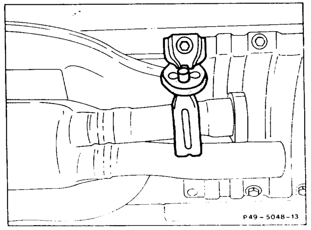
Fig. 1
Fee
time RA 07.3.1142/17
Parts
Qty. Part no. Designation
Rubber ring on center muffler (KAT/without KAT) 129 492 00 44 —~ oe oot Rubber ring on front muffler (without KAT) 129 492 00 82 Bracket at tunnel closing plate 129 492 08 41 Bracket at exhaust pipe (weld on) 129 492 32 41
Complaint:
Front exhaust pipe making contact with cross member of front axle
Model 126.02 RUF
Cause The exhaust system moves forward as a result of the high thermal stresses when driving extremely sharply. Remedy If the front exhaust pipes are greatly deformed, replace front exhaust system. Modified front exhaust systems have been available since mid May 1987 (part no. 126 490 95 19).
PR
wiimp §=RA 07.3.1142/18
Modification Notes Engine 103 Combustion IV KE Injection
This film replaces the film 07 102 2063 02.
The contents of the films 07 102 2025 03, 07 102 2061 03, 07 102 2062 03 and 07 102 2063 03 have been revised, with the following contents:
Film no. 07 102 2025 03 Combustion |! Group 07.3 Mechanical/Electronic gasoline injection system (KE injection) Test and adjustment operations (except Testing electrical components of KE injection system) Programed repairs, group 07.3
Film no. 07 102 2061 03 Combustion Il Group 07.3 Mechanical/Electronic gasoline injection system (KE injection) 07.3-121 Testing electrical components
Film no. 07 102 2062 03 Combustion Hl Group 07.3 Mechanical/Electronic gasoline injection system (KE injection) Removal and installation operations Group 09 Air cleaner Group 14 Intake manifold, exhaust manifold, emissions control system Group 15 Electrical system engine (ignition system)
Film no. 07 102 2063 03 Combustion IV Group 30 Accelerator control Group 47 Fuel system Group 49 Exhaust system Programed repairs, groups 09, 14, 15, 30, 47 and 49
whi §=RA 07.3.1142/1
The operation descriptions have been matched to the „Operation texts and work units” and „Standard texts and flat rates”, respectively.
Always refer to the microfiche “Operation texts and work units” and „Standard texts and flat rates”, respectively, for the operation numbers for the repair order.
A list of revisions and additions is given below in brief. The Service Information Bulletins 00/82, 07/7, 07.3/45, 07.3/47, 14/15, 15/43, 15/52 and 47/13, Technical Modifications, Subjects of Up-to-date Troubleshooting and Troubleshooting, as well as the Introduction into Service „New Features Passenger Cars June 1990 and Model Year 1991 (A> @S & @) G) G5” have been incorporated.
Coordinates
Revised:
30-1010 Adjusting accelerator control 00… 0. eee eee ee eee A 2 47-4100 Removing and installing fuel tank 2.2… 0… eee N 8
Included for the first time:
Programed repairs, Groups 14, 15, 30, 47,49 «0.2… eee H 16
Note For all the function descriptions see Repair Instructions „Function description KE injection”.