Removing and installing crankshaft gear
WIS 05-4600
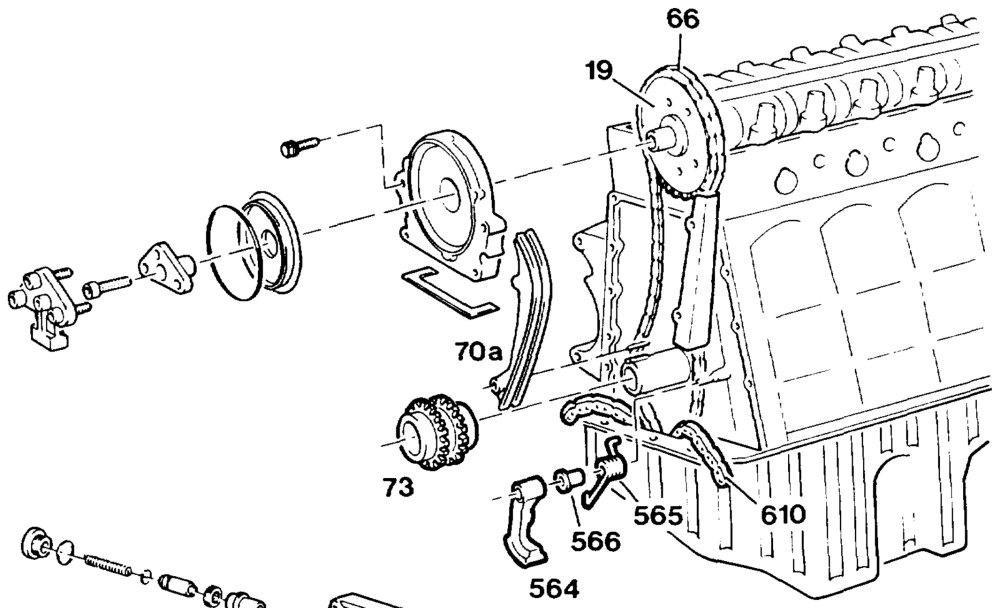
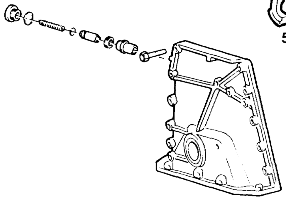
Preceding work: Operation no. of operation texts and work units or standard texts Warning instructions when hood open (01-0085). and flat rates Timing case cover removed (01-2100).
Pos – 0119–59
Piston of cylinder 1 200 ee ee set to TDC (step 1). Tensioning rail (70a) …………-2.—20— remove, install (05-3300) (steps 2, 20). Tensioning bracket (564), spring (565) with bush (566) «2… …..2…-0. 002022 ee pull off (steps 3 – 4). Oil pump chain (610) ………………4.. grind open rivet link pins (step 5). Timing chain (66) relative to camshaft gear (19) . mark, take off (step 6). Crankshaft gear (73) …………….20085 pull off with puller 615 589 01 33 00 (step 7).
wuim =—-RA 05.1123-4600/1
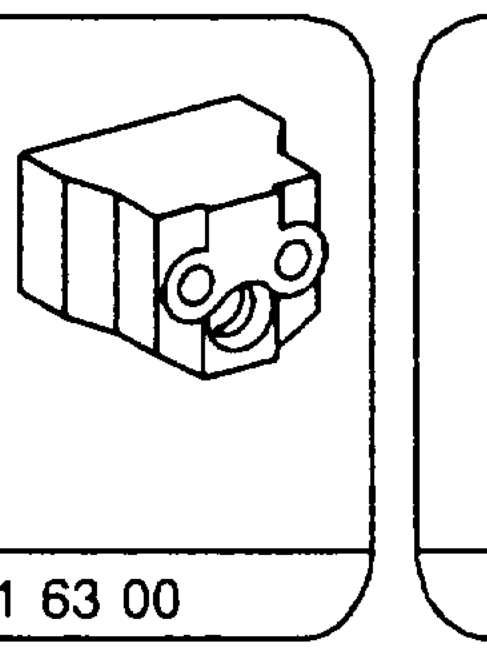
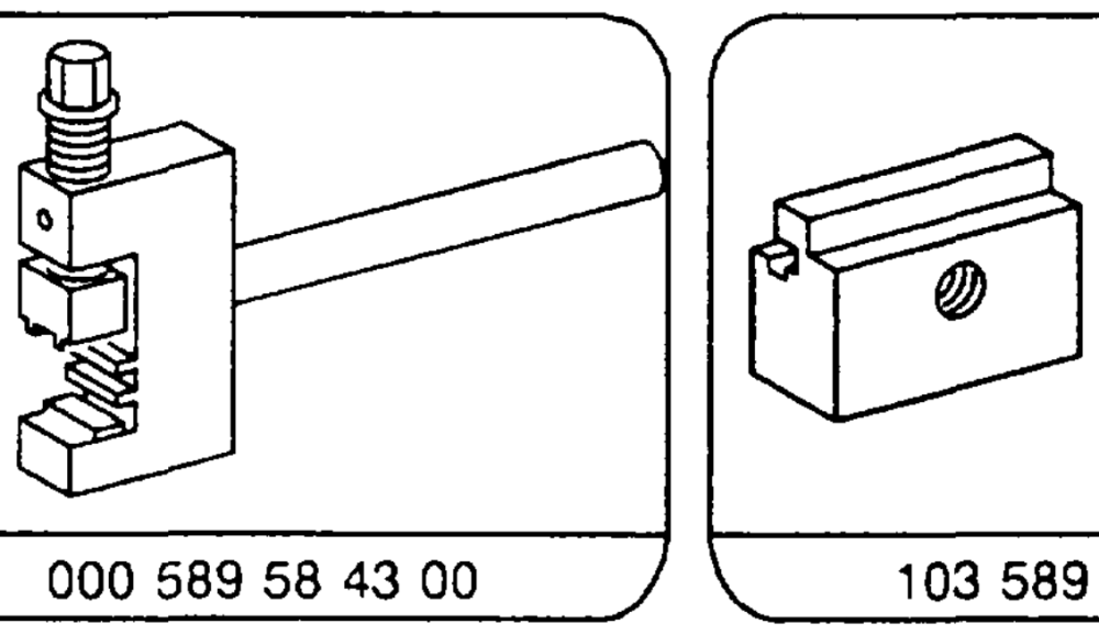
Crankshaft gear (73) heat, fit on (step 8). Timing chain (66) fit onto camshaft gear (19) (step 9). Oil pump chain (610) fit onto crankshaft gear (73) and insert rivet link into oil pump chain from behind (step 10). Insert plate into rivet set 103 589 01 63 00 and into riveting tool 000 589 58 43 00, press on (steps 11 — 15). rivet individually (steps 16 – 18), 25 Nm. Rivet link pins of oil pump chain Spring (565), bush (566) and tensioning bracket (564) install (step 19). Installation in the reverse order.
check for signs of leaks.
Special tools
c >
01 615 589 01 33 00 /
Note When renewing a crankshaft gear, timing gear and camshaft gear must also be renewed.
wake = =RA 05.1123-4600/2
Removal
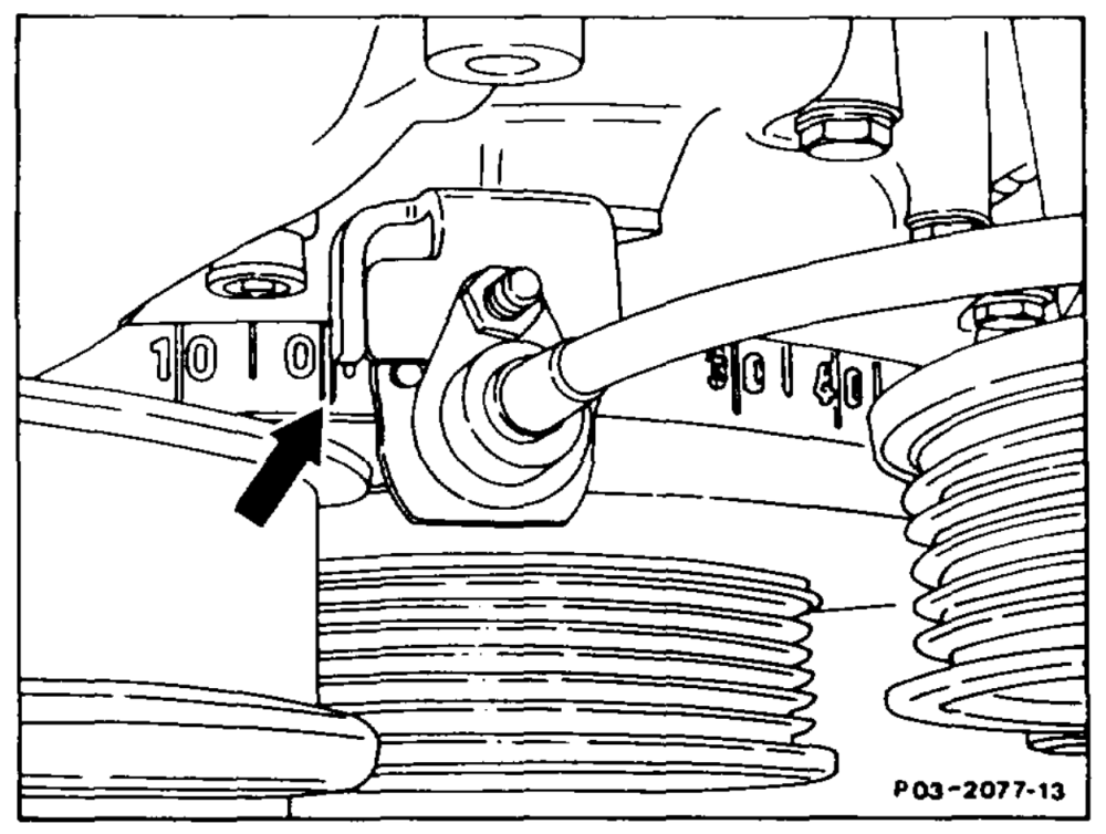
1 Set piston of cylinder 1 to TDC.
2 Remove tensioning rail (05-330).
3 Cover over oil sump with clean cloths.
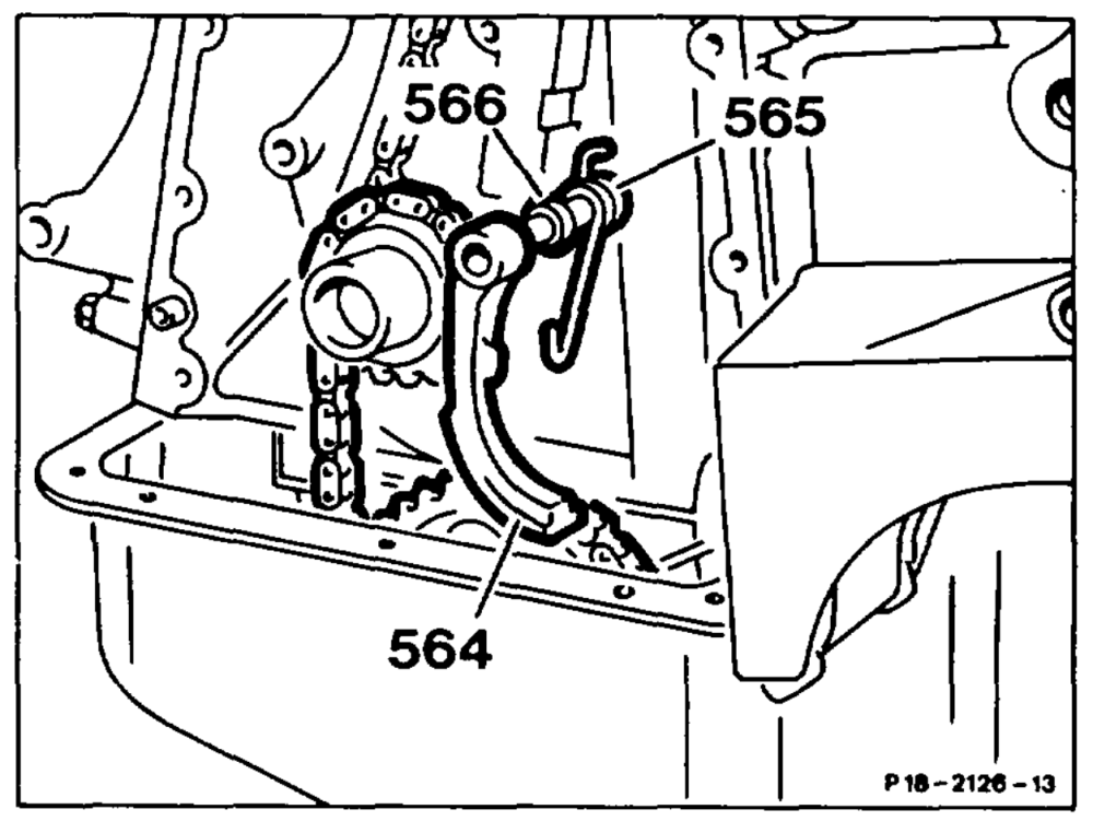
4 Pull off tensioning bracket (564), spring (565) together with bush (566).
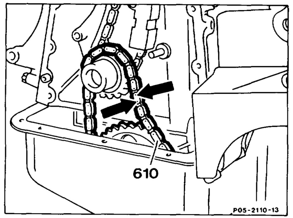
5 Grind open both rivet link pins (arrows) on a double link of the oil pump chain (610). Press out ground-open double link.
Note Do not take oil pump chain off the oil pump drive gear, tie on left and right with wire.
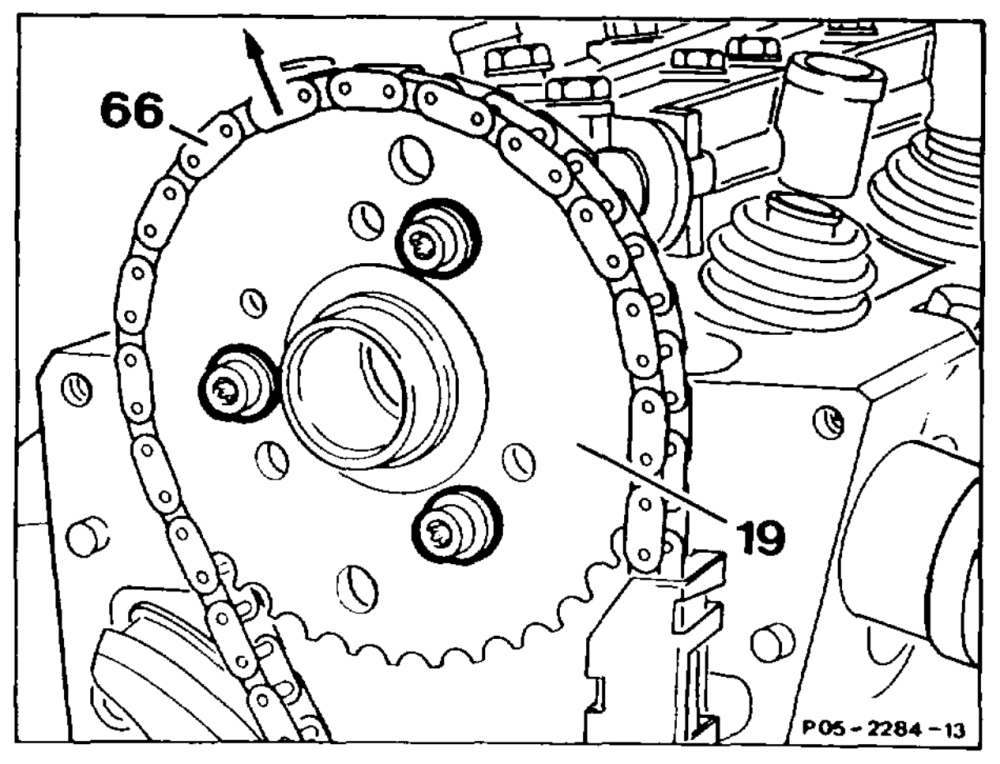
6 Mark position of timing chain (66) relative to camshaft gear (19) with a coloured pen. Take timing chain off camshaft gear (19) in direction of arrow.
wai =A 05.1123-4600/3
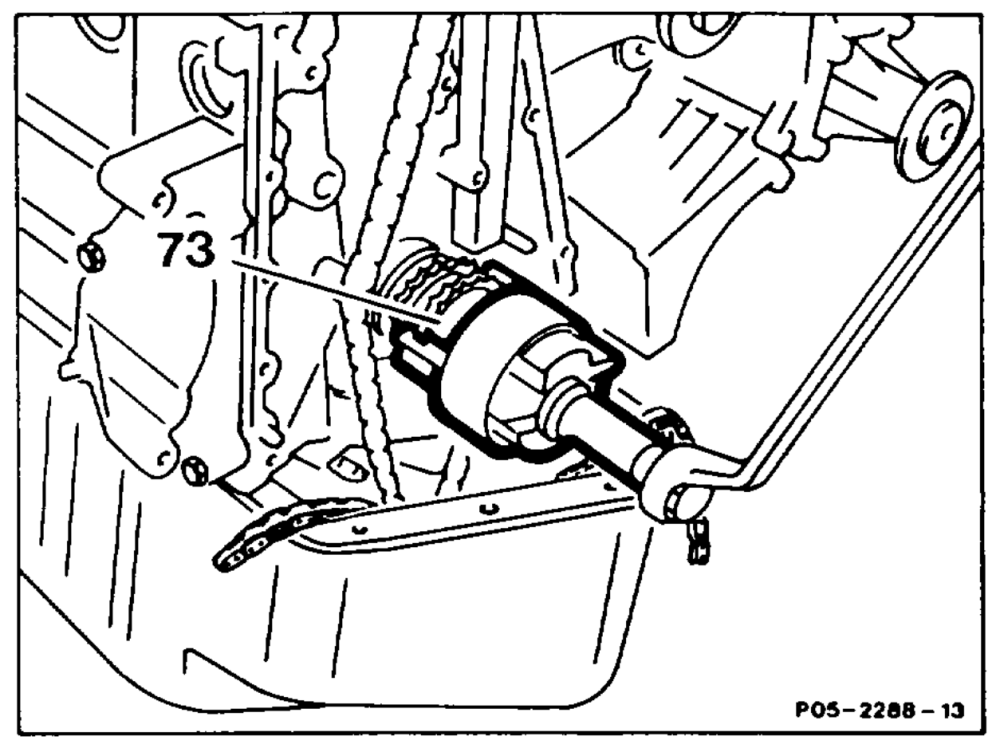
7 Pull off crankshaft gear (73) with puller 615 589 01 33 00.
Installation
8 Heat crankshaft gear to approx. 50 °C and fit onto the crankshaft. Pay attention to the Woodruff keys.
9 Fit timing chain onto the camshaft gear.
Note Pay attention to coloured marking.
10 Fit oil pump chain onto the crankshaft gear. Insert rivet link into the oil pump chain from behind.
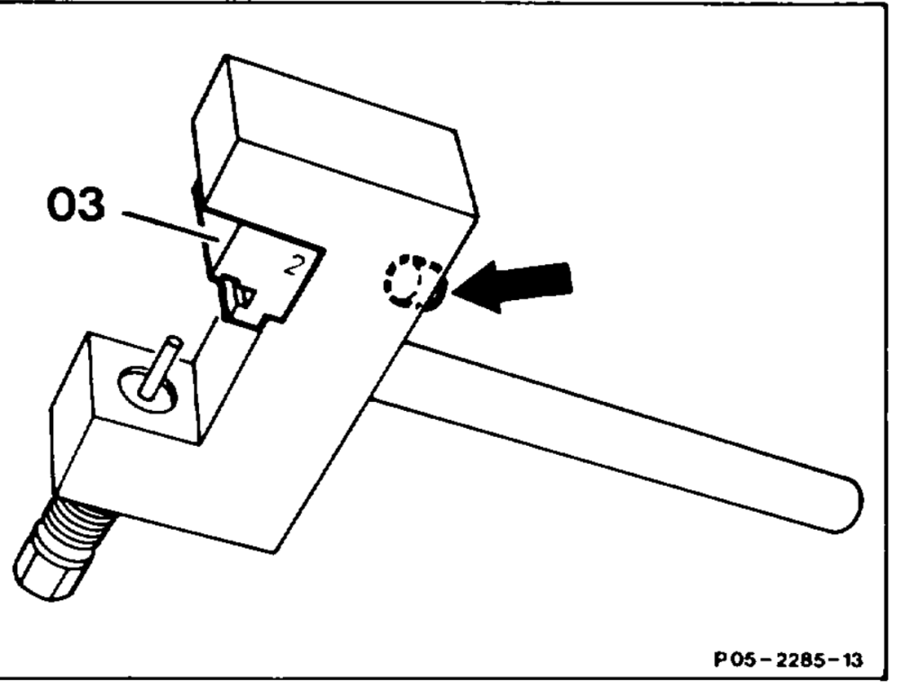
11 Insert cheeks (03) 103 589 01 63 00 into the riveting tool 000 589 58 43 00 as shown in drawing and tighten with the screw (arrow).
Note The figure 2 is stamped on the side of the cheek (03) 103 589 01 63 00.
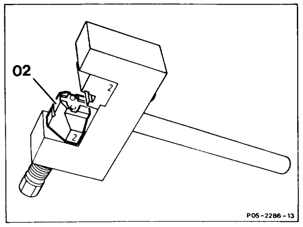
12 Insert moving thrust piece (02) 103 589 01 63 00 with the figure 2 into the riveting tool 000 589 58 43 00 as shown in the drawing.
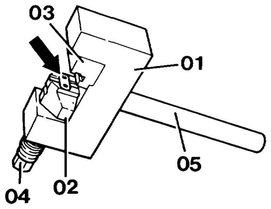
piece (02) 103 589 01 63 00 (magnetic surface).
POS-2123–13
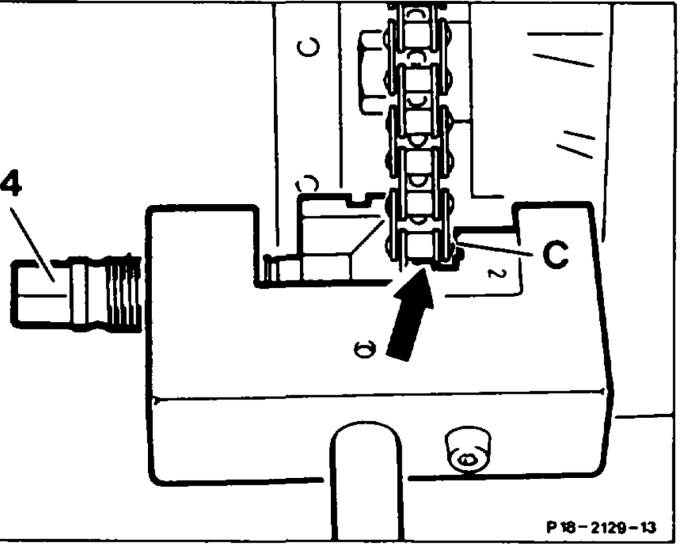
14 Fit web (arrow) onto both rollers on the link.
Note Rivet heads of rivet link pins must be guided in the slot (C). 04
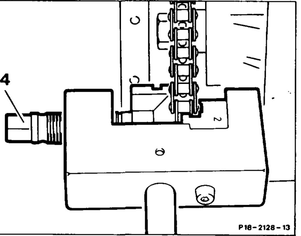
15 Screw in spindle (04) until a firm resistance is felt.
Note When screwing in, ensure that the pins of the 04 link are inserted into the holes of the plate.
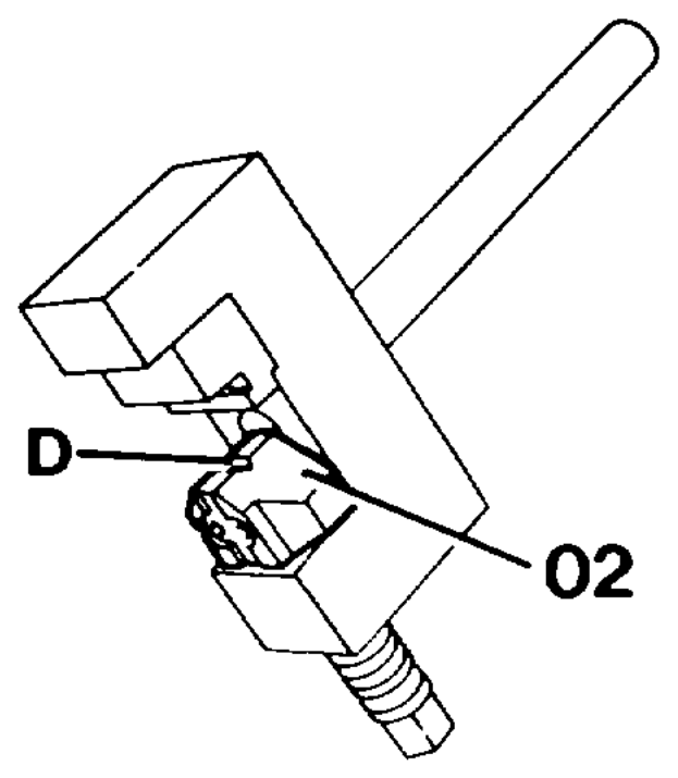
16 Take off riveting too! 000 589 58 43 00 and change over the moving thrust piece (02) 103 589 01 63 00 onto the rivet profile (D).
PO5-2125–13
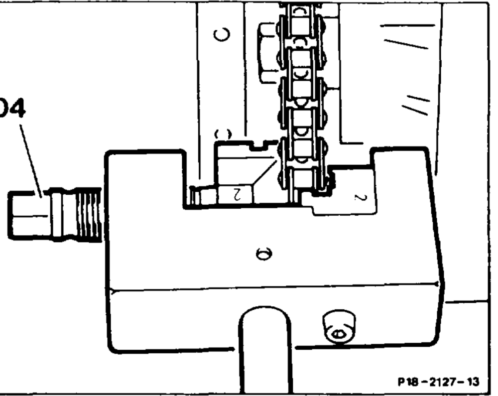
Rivet pins of the rivet link individually by tightening the spindle (04) to 25 Nm.
18 Check riveting; re-rivet if necessary.
19 Install spring, bush and tensioning bracket.
20 Install tensioning rail (05-3300).
Installation is performed in the reverse order.
21 Check for leaks with engine running.