Removing and installing camshaft
WIS 05-2200
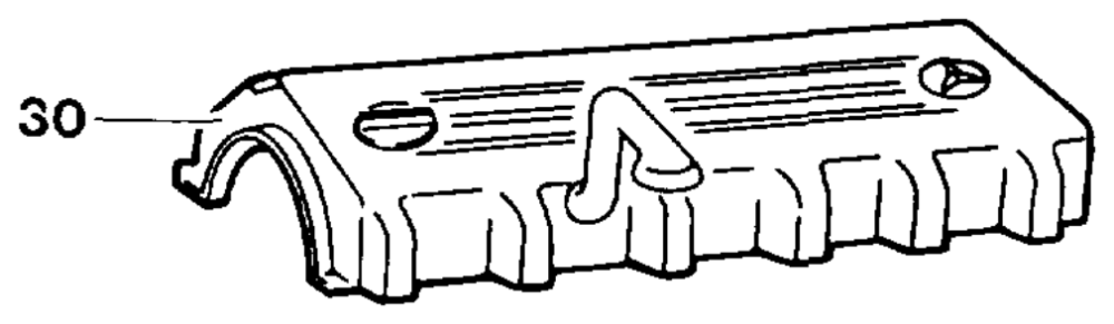
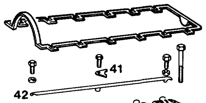
Preceding work: Operation no. of operation texts and work units or slandard texts Air cleaner removed (09-1051). and flat rates Cylinder head cover removed (01-0500) 05-5521, 05-5541, 05-6292 up to 05-7050 Front cover at top removed (01-2120). Camshakt oil pipe removed (18-4200)
POS-0112-57A
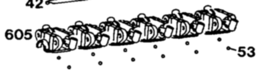
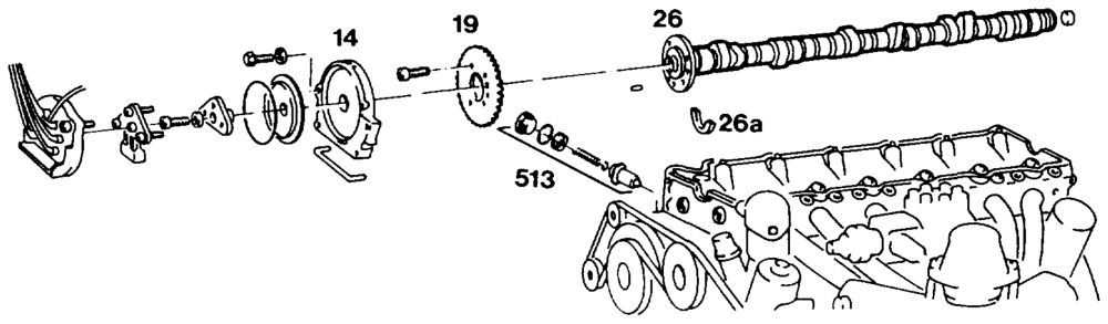
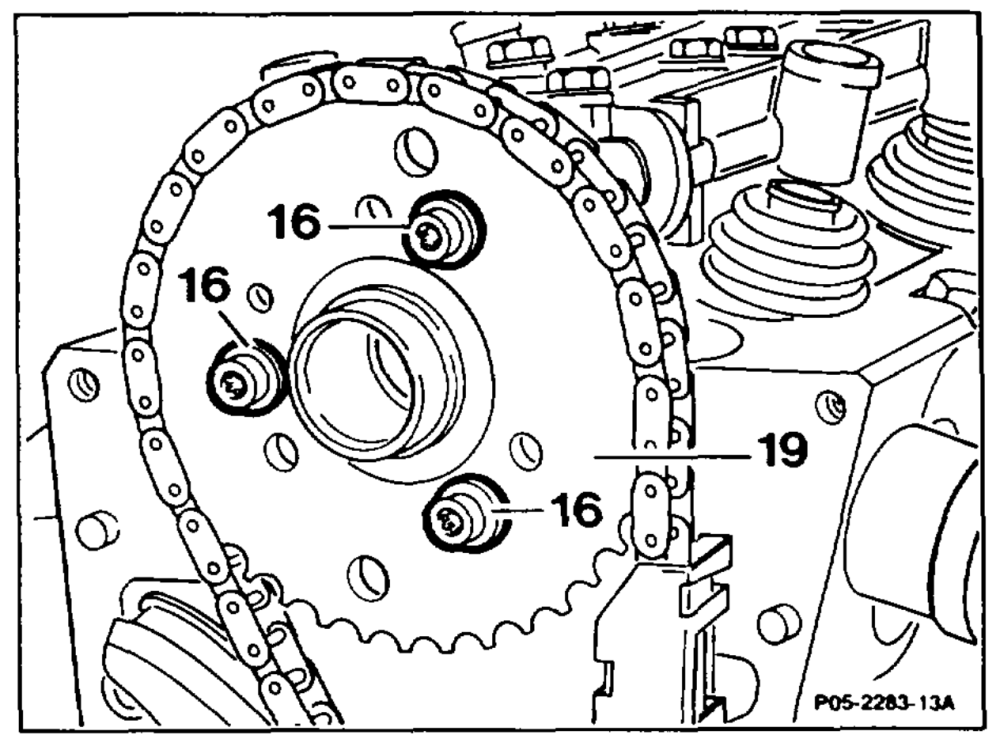
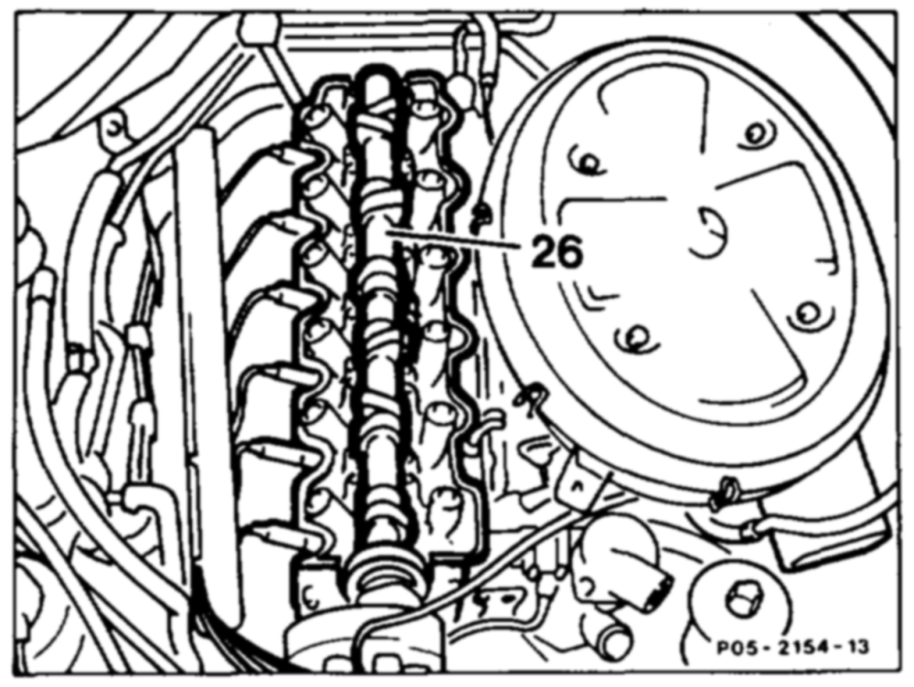
Piston of cylinder 1 set to TDC (step 1) Camshaft gear (19) ………..-.-….–6mark relative to camshaft (26) (step 2) Chain tensioner (513) …………….-200remove, install (05-3100) Camshaft gear (19) …………—…000remove, install (step 4, pay attention to note) All camshaft bearing caps (605) together with rocker arms 000000 e eee remove, install (05-2190) Camshaft and rocker arm friction surfaces ….. oil Camshaft (26) ……..-.-2. 000020. e ee eee lift out, insert. Pay attention to thrust washer (26a) (step 6)
wii =RA 05.1123-2200/1
Basic position of camshaft (26) …………. check (05-2230). Camshaft lubrication when engine running ….. check (step 10).
Notes
Modified camshaft gear
Modified camshaft gears with holes (previously slots) and securing bolts with a higher strength of 10.9 are fitted in order to avoid the securing bolts slackening.
Camshaft gear 2nd version, production breakpoint: 06/1985
Model Engine Engine end no. Vehicle ident end no. man. transm. autom. transm. A F
124.030 103.980 000731 003012 047987 . not recorded
Modification to camshaft and camshaft gear
The modified shape of cam permits an engine speed which is 200 rpm higher.
The mounting holes in the camshaft gear have a diameter 7.5 mm (previously 6.4 mm). The camshaft flange is provided with an M7 thread (previously M6) for attaching the camshaft gear. The tightening torque is 16 Nm (previously
10 Nm).
wae = RA 05.1123-2200/2
M7 thread in camshaft flange, production breakpoint: 05/1986
Model Engine Engine end no. Vehicle ident end no. A F man. transm. autom. transm.
107.041 103.982 000495 002463 050167
124.026 103.940 004621 007048 247878 *
124.030 103.983 005188 029831 249195 124.090
126.020 103.941 000951 003725 254136
126.024 103.981 001986 015232 255612 126.025
201.029 103.942 from start of production 229220 not recorded
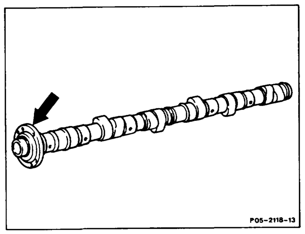
The camshaft code number is stamped in the flange (arrow).
Camshaft with modified timing
Camshafts with modified timing are installed in engines fitted with automatic transmission. The inlet cams are retarded 5° CA (code number 53).
waite =RA 05.1123-2200/3
Inlet camshaft + 5°, production breakpoint: 05/1989 Model Engine Engine end no. Vehicle ident end no. man. transm. autom. transm. A F
124.026 103.940 . 066138 * .
124.030 103.983 * 168786 * , 124.050 124.090
124.230 103.985 * 007837 * * 124.290
201.029 103.942 030695 * * not recorded
Modifications to camshaft, rocker arms and
driver
Since 03/1989 chilled cast camshafts and rocker arms with hard metal friction surface have been fitted to all engines. See (05-2320) for production breakpoint.
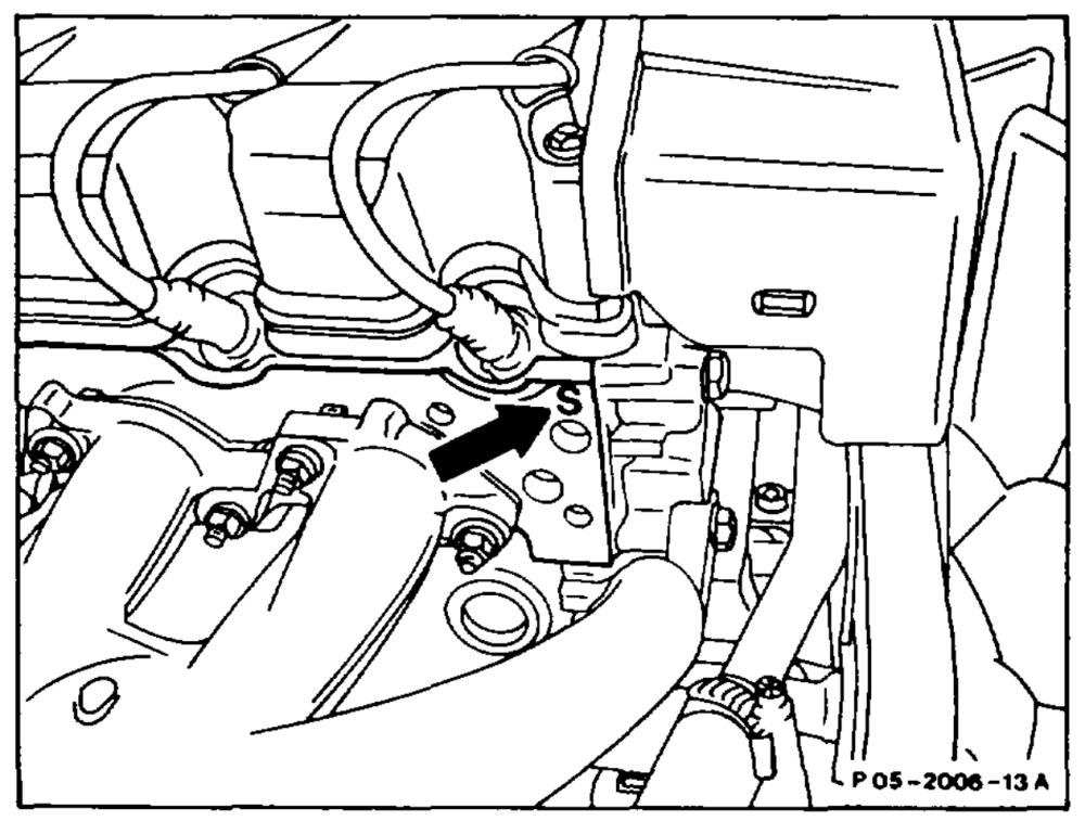
Provisional identification: „S” (arrow) on contact surface of cylinder head at exhaust end. If chilled cast camshaft is retrofitted, the engine in question should be identified with an “S”.
suite = RA 05.1123-2200/4
AN When performing repairs, only chilled cast camshafts may be installed. The chilled cast camshafts may only be fitted together with rocker arms with hard metal coating (standard as of 03/1989) and the modified driver (see 05-2170) for the distributor rotor.
Inductively hardened camshafts may only be used in combination with hard chrome-plated rocker arms (standard up to 02/1989).
{f bearing fretting or severe scoring exists, the camshaft bearings in the cylinder head and in the rocker arm bearing brackets can be widened 0.5 mm by drilling and a camshaft with oversized bearing journals installed.
After damage to a cam (eg. worn cams), all the affected timing parts (hydraulic elements, valves, valve springs, valve heads and valve cotters) should be checked for signs of damage.
If individual rocker arm bearing brackets are renewed, all the bearing brackets must be tightened to specification and the camshaft checked to ensure that it moves freely (rocker arms removed).
If camshaft damage has occurred as a result of an oil deficiency resulting from a loose oil nozzle return lock without stop shoulder, an oil nozzle return lock with stop shoulder must be fitted (standard as of 12/1986) (18-4150).
aime = RA 05.1123-2200/5
Removal, instaliation
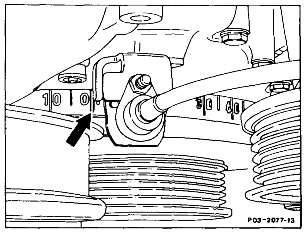
1 Position piston of cylinder 1 to TDC (arrow).
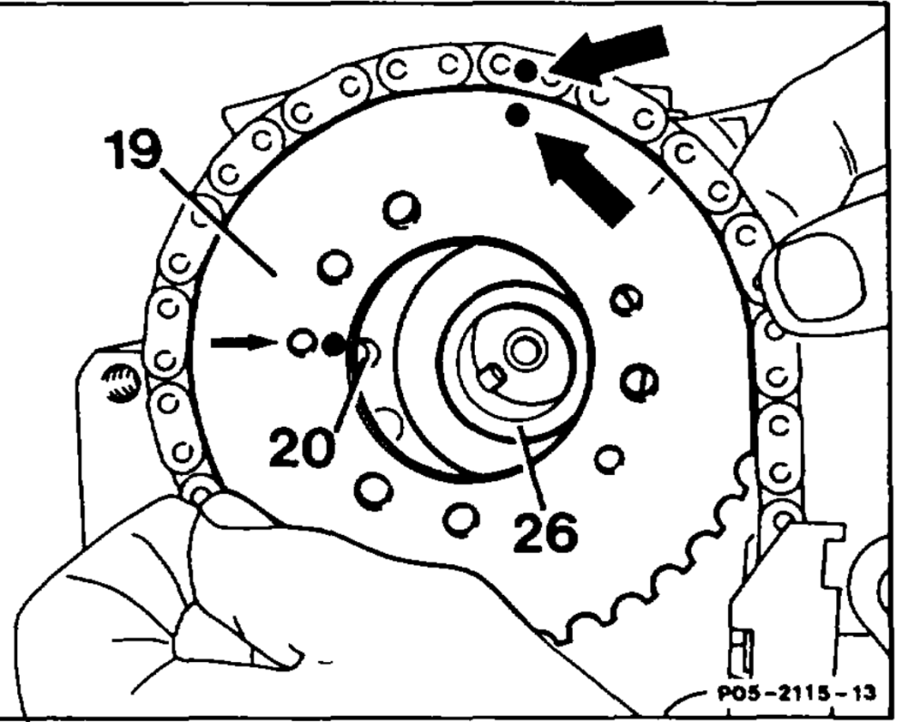
2 Mark position of camshaft gear (19) relative to camshaft (26) and to timing chain (arrows). This is done by applying colored markings next to the locating pin (20) at the camshaft gear (19) and at the timing chain.
Note If the camshaft gear is replaced, the colored markings must be applied to the same point on the new camshaft gear (19).
3 Remove chain tensioner (05-3100).
4 Unbolt camshaft gear (19) and pull off by hand.
Tightening torque Hexagon socket bolts M6 11 Nm Torx bolts M7 16Nm
Note
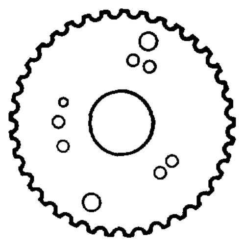
The camshaft gear with 3 slots (A) 1st version should be replaced with the camshaft gear A B 2nd version (B) with 3 holes each © 6 mm when performing repairs. oO The camshaft gear 2nd version (B) can be used ° ° in place of the camshaft gear 3rd version with ° C) 0 3 holes each © 7 mm when performing repairs; SY 5° in this case, the 3 holes @ 6 mm should be widened to © 7 mm. POS 5012.13
wae =RA 05.1123-2200/6
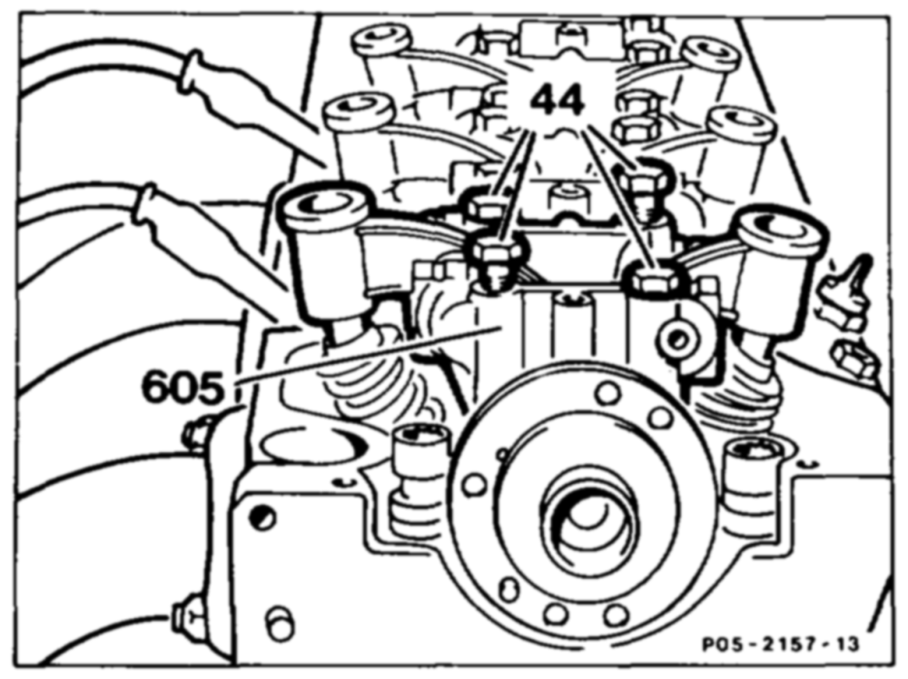
5 Unbolt camshaft bearing caps (605) (05-2190).
6 Lift out camshaft (26).
Note Pay attention to the thrust washer at the front (axial mounting) when lifting out camshaft.
7 Oil camshaft bearing journals.
8 install in the reverse order.
9 Check basic position of camshafts (05-2230).
10 Check oil supply (direction of spray) of camshaft at idle speed.