Removing and installing crankshaft position sensor
WIS 15-2133
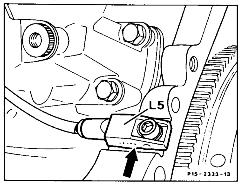
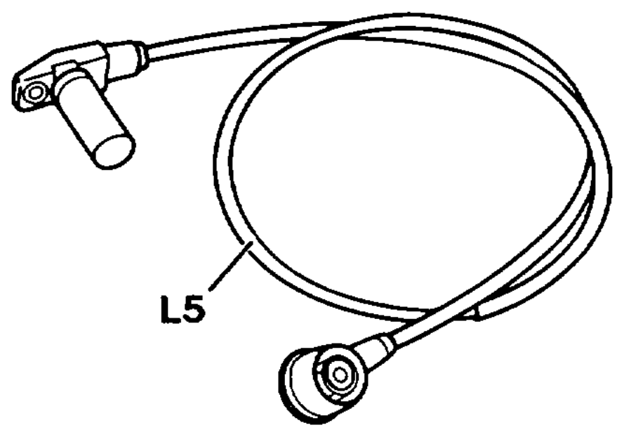
Operation no. of operation texts and work units or standard texts and flat rates: 15-2133.
P15-2136-134 P15-5001–53
Screw (arrow) 66. ee eee unscrew, screw in. Tightening torque 10 Nm as reference value. Crankshaft position sensor (L5) …………. remove, install. Take cable to EZL/AKR control unit out of cable shaft. KE control unit fault memory read, erase if necessary. (see Diagnosis Manual Engine, Volume 2, Register 0).
Note Stored faults which may occur because of disconnected cables or simulation during test work, must be erased in the fault memory after completing all work.
AN Vehicles with manual transmission as of 08/89: On engines with two mass flywheel (ZMS), a spacer disc must be placed below the crankshaft position sensor (L5) otherwise the segment will rub on the sensor.
wim RA 15.1132-2133/1
Note
Model 124
Crankshaft position sensors of AB-Elektronik or Bosch are installed alternatively.
Production breakpoint: January 1986
Model Engine Engine end no. Engine end no. manual transmission automatic transmission
124.026 103.940 002636 003779
124.030 103.983 002892 018378
wile §=RA 15.1132-2133/2